Step 3
Commissioning in
Kuka WorkVisual
Importing device description files
▶ Download the EtherCAT device description files, also known as ESI File from the product page.
▶ Close any open projects
▶ Select the menu sequence File > Import/Export and select Import device description file
▶ Click Next, then Browse... ,select type: EtherCAT ESI and navigate to the directory of the downloaded file and open.
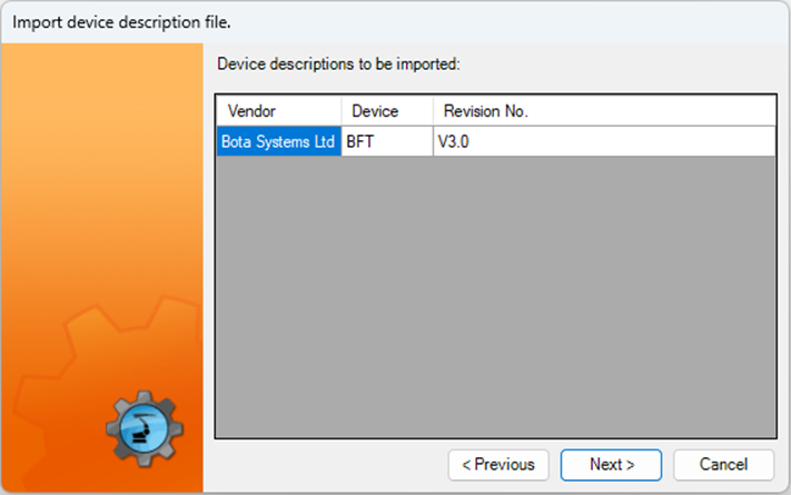
▶ Confirm with clicking Next >, the list below will appear with one item to be imported. Click Next > and Finish
▶ The imported files are now available in the DTM Catalog.
Inserting devices manually in the bus
▶ Make sure that the above step has been successfully followed.
▶ Make sure that the field bus master is inserted in the bus structure.
▶ Make sure that the the robot controller has been set as the active controller.
▶ Expand the tree structure on the Hardware tab in the Project Structure window and add the EtherCAT bus if required
▶ Search for Vendor: Bota System Ltd. and drag the device onto the field bus master in the Hardware tab (repeat same for other devices)
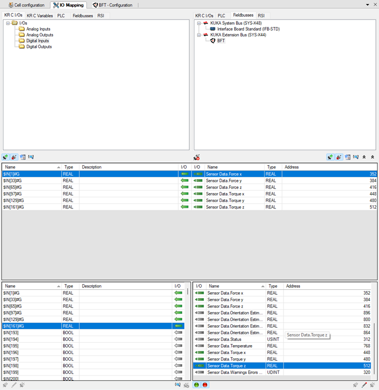
Mapping input to output
This procedure is required to assign the inputs and outputs of the force torque sensor to the inputs and outputs of the robot controller.
▶ Make sure that the robot controller has been set as the active controller
▶ Make sure that the bus configuration in WorkVisual corresponds to the real bus configuration
▶ Make sure that all field bis devices are configured
▶ Click on the Mapping editor button, on the KR C I/Os or RSI tab in the left half of the window and select the area of the robot controller that is to be mapped to the sensor Digital inputs.
▶ The signals are displayed in the bottom area of the the I/O Mapping window.
▶ Select the device on the field buses tab in the right half of the window. The signals of the device are displayed in the bottom area of the I/O Mapping window.
▶ Drag the input or output of the device on the signal of the robot controller. The signals are now mapped (see picture)