
Step 1
Sensor
Installation
▶ Make sure the robot is deactivated and there is no power.
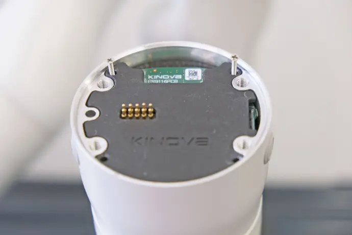
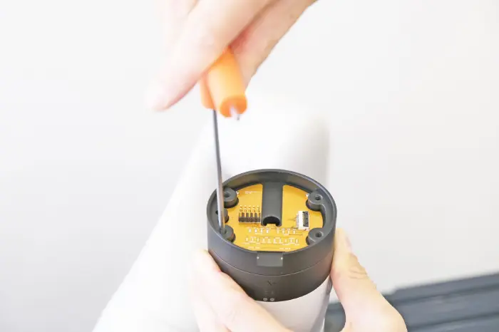
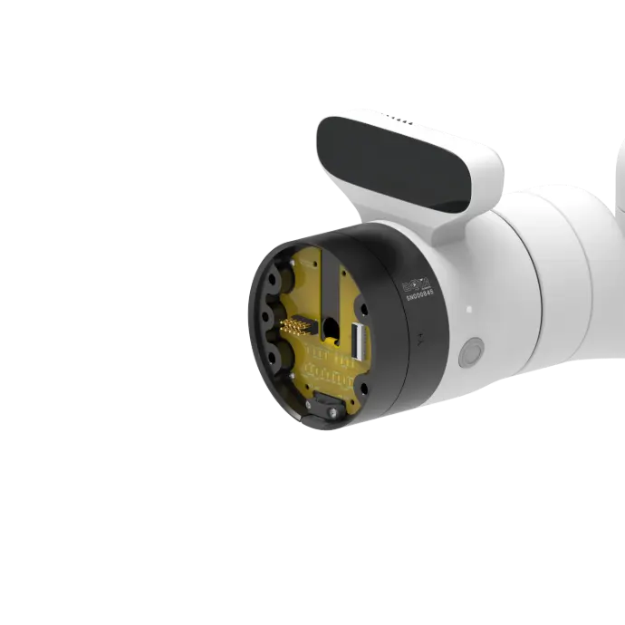
▶ Remove the robot's end effector cover (blue cover) by removing the 4xM5 screws with a 4 mm allen key.
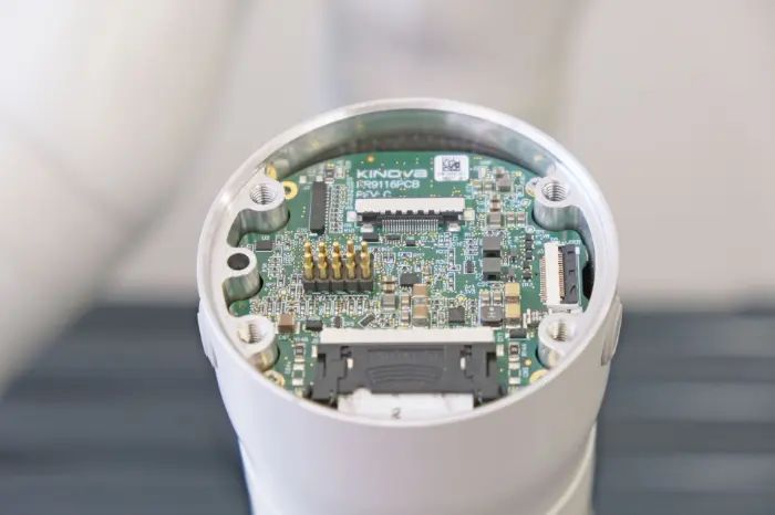
▶ After revealing the electronics remove the black cover to gain access to the 20-pin connector, using a PH1 Philips screw driver
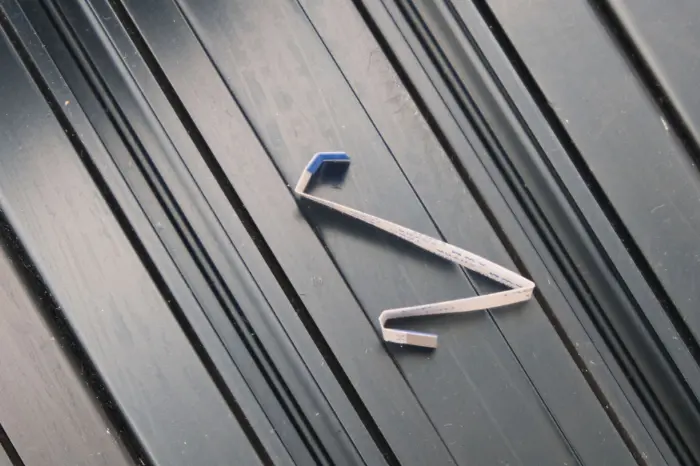
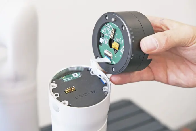
▶ Pre-bend the ribbon cable that came with the kit like on the picture, and insert the short bend on the robot's connector.
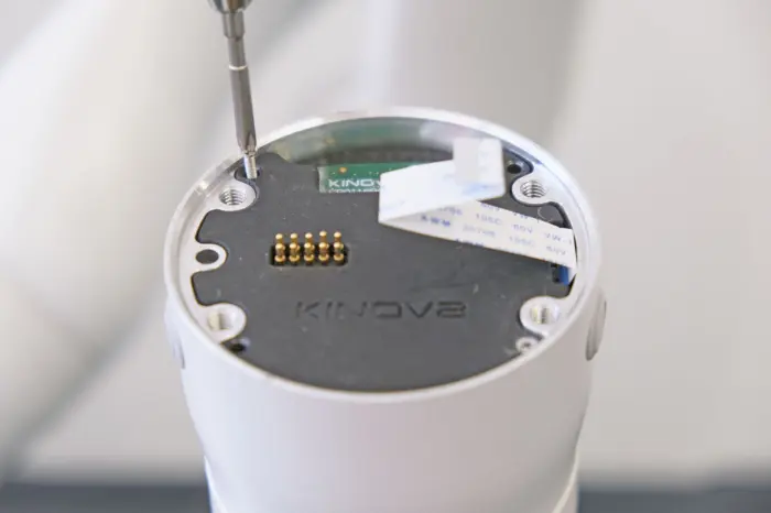
▶ Re-attach the electronics cover of the robot to protect the electronics and carefully attach the other end of the ribbon cable to the sensor's 20-pin connector
▶ Align the sensor's pin with the robot's pin hole and with the included 3mm allen key attach the sensor to the robot. The allen key fits through the sensors threads, do not over-tighten the screws.
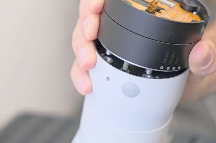
ONLY USE THE PROVIDED TOOL TO TIGHTEN
Step 2
Tool
Installation
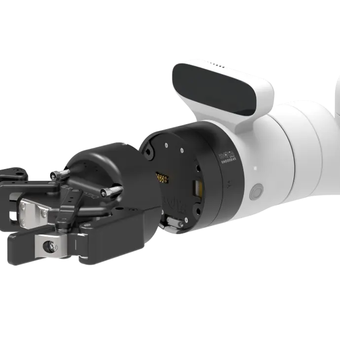
▶ A variety of tools ca be mounted on the sensor choose from the options the most suitable for your application
Option 1
RobotIQ
Gripper
▶ Mount the gripper. Align the gripper's pin with the sensor's pin hole and firmly hold the gripper while fastening the screws.

Option 2
Tool with ISO Flange
▶ Install the ribbon cable on the sensor and the ISO adapter.
▶ Mount the ISO adapter, align the adapter's pin with the sensor's pin hole and firmly hold the adapter while fastening the screws.
▶ Mount the tool on the ISO adapter with 4xM6 screws and a 6mm pin
▶ Connect the tool to the adapter's
8-pin M8 connector for power (5,12,24V options), GPIOs, RS485 (connected to UART) or the 4-pin M8 Ethernet connector.
Option 3
Custom
Tool
▶ Remove the sensors' plastic cover to access the solder pads and the through-hole tunnel of the sensor.
▶ Connect to the robot's GPIOs, UART, Ethernet, I2C and 24V signals either by solder pads or the 20-pin connector.
▶ Mount the tool. The sensor tool flange is identical mechanically and electrically to the robot's.
See robot's user manual
Step 3
System Setup &
Commissioning
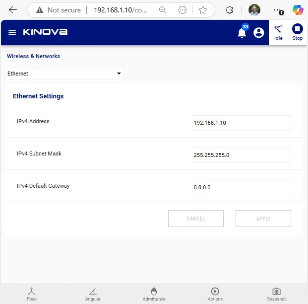
▶ Establish communication between the robot base and the controller machine (PC). Power on the robot, connect an ethernet cable between the robot base and the machine and configure the machine's network settings as following:
     IP: 192.168.1.1
Gateway: 192.168.1.10
 Subnet: 255.255.255.0
⚠️
The above configuration works for the default Kinova Gen3 setup, if different IPs are used configure accordingly
To confirm robot connectivity, visit the robot's web interface through a browser using this link
▶ Additionally, a routing directive is needed to allow proper message routing.
for Linux machine, the following command allows the routing:
sudo ip route add 10.20.0.0/24 via <ROBOT_IP> dev <Ethernet_interface>- <ROBOT_IP> is 192.168.1.10 by default.
- <Ethernet_interface> is usually eth0 use the following comand to find out yours.
ip a▶ The sensor is connected to the Ethernet interface of the robot's flange interconnect module. The sensor comes preconfigured with ethernet communication enabled and no additional configuration is needed. To ensure communication with the sensor
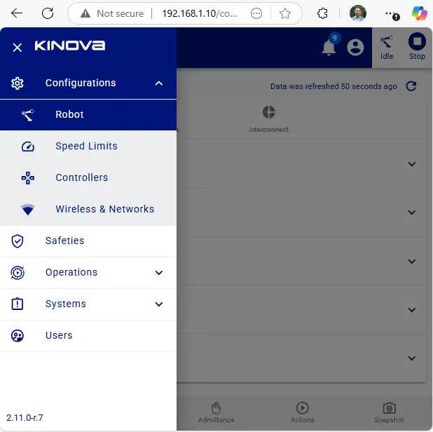
▶ In the robot, the feature that allows the Ethernet bridge between the interconnect and the base must be enabled. This can be done from the web interface of the robot (see pictures below) or following the example "109-Gen3_ethernet_bridge" from the official Kortex API examples.
▶ Finally, the sensor can be read using our FT Sensor Driver, available for C++, Python and ROS2.
The JSON configuration file that is passed to the driver should follow the template of Bota Socket, indicating the correct sensor IP address (e.g. 10.20.0.201).
Step 4
Software
Integration
ℹ️
The F/T sensor is a network devices and can be used independently of the robot, as long as the robot is enabled.
▶ Before integrating the sensor download the the config file below containing the sensor's configuration.
Config File to be used in the next steps:
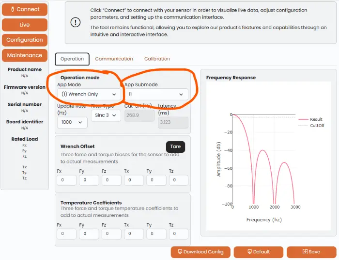
ℹ️
In this file the sensor has been configured to provide Force/torque data only (no IMU data) with a update frequency of 1000Hz, these properties are controlled by the "app_mode" and "app_submode" respectively and to modify them consult the online config tool (picture below) or the sensor's user manual.
▶ Choose your environment and architecture from the list below. An advance driver with examples are implemented for all the options and follow the specific steps within each option.
For information on how the driver works, see the driver documentation here
Option 4
ROS Control
▶ Find detailed information about the ROS2 control driver in this link.
▶ Follow the instruction of the ros2_control examples to get measurements, through ros2_control hardware interface

Option 3
ROS Node
▶ Find detailed information about the ROS2 driver in this link.
▶ Follow the instruction of the ROS 2 driver examples to get measurements, through ROS topics
Option 1
C++ Driver
▶ Follow the instruction of the C++ driver to get measurements. There are available for Windows and Linux in x86_64 and aarch64 architectures.
▶ Download the driver for Linux & Windows from the driver's page

Option 2
Python Driver
▶ Follow the instruction of the Python driver to get measurements. There are available for Windows and Linux in x86_64 and aarch64 architectures.
▶ Download and Install the driver using the following command in command line with python and pip installed
pip install bota-driver