
Step 1
Unboxing
▶ Make sure all of the parts included in your order has been included in your delivery and there are no signs of damage.
▶ Identify the product Generation. Check on the sensor body for the product name. It starts with "BFT-" for example "BFT-ROKS-SER-M8". Make sure your product is part of the list below.
Generation | Product Name |
Gen 0, | BFT-ROKS-SER-M8 BFT-ROKA-SER-M8 BFT-MEDS-SER-M8 BFT-MEDA-SER-M8 BFT-DENS-SER-M8 BFT-SENS-SER-M8 BFT-MENS-SER-M8 BFT-LAXS-SER-M8 BFT-MEGS-SER-M8 BFT-MIPS-SER-CG |
▶ Select from the options below the one that best matches your kit.
Step 2
Electrical
Integration
Serial with USB-to-Serial Adapter
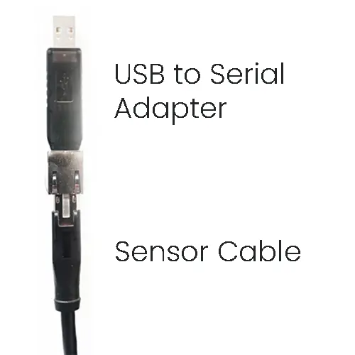
▶ Connect the provided cable to the sensor, aligning the key on the cable and sensor connector. Screw the locking nut, till the cable is not moving.
▶ Connect the other end of the sensor cable to the USB to Serial Adapter.
▶ Plug the USB to Serial adapter to a computer. Shortly the Green LED of the sensor should come up.
▶ The device will appear as a Serial port to the comptuter. For linux with the name /dev/ttyUSB* and for Windows as COM*.
If the device do not appear automatically in Windows, install the drivers. Download here
Serial with Breakout board (Advanced)
▶ Connect the provided cable to the sensor, aligning the key on the cable and sensor connector. Screw the locking nut, till the cable is not moving.
▶ Connect the other end of the sensor cable to the USB to Serial Adapter.
▶ Plug the USB to Serial adapter to a computer. Shortly the Green LED of the sensor should come up.
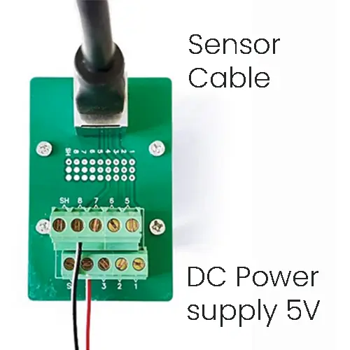
▶ Follow the pinout from the table below to connect the sensor to your RS422 compatible device.
Pin | Signal Function |
1 | RS-422, TX+ (Sensor output) |
2 | RS-422, TX- (Sensor output) |
3 | RS-422, RX+ (Sensor input) |
4,5 | VSS+ (5V) |
6 | RS-422, RX- (Sensor input) |
7,8 | VSS- (GND) |
SH | Sensor Shielding, |
Step 3
Mechanical
Integration
Please comply with the following requirements to ensure your sensor’s measurement quality
▶ Avoid mounting with non-rigid parts like 3D printed adapters.
▶ Clean the mounting surfaces from any dirt and debris.
▶ Do not under- or over-tighten the fasteners (see our user manual)
▶ Fix the sensor cable safe and steady on your system such that it does not apply any force to the sensor.
Step 4
Software
Integration

Bota Systems AG has developed a user-friendly driver to simplify the integration of sensors into your applications. The driver is a plug-and-play software package that makes configuring and reading data from Bota Systems' FT sensors easy and efficient for the most popular platforms, including C++, Python and ROS2. For more information see here.
This guide will integrates the sensor with a Python software, for a closed-loop control application that runs in 100hz and communicates with the sensor with Baudrate 460800.
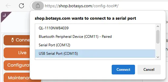
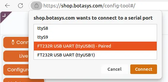
▶ With the Sensor connected to a Computer with Internet access navigate to the Config Tool
ONLY, Chrome, and Edge Browsers are supported.
▶ Click on the button "Connect" on the top left corner and select the correct port. Will appear as a "USB to Serial (COM*)" for Windows and FT232R USB UART (ttyUSB*) for Linux
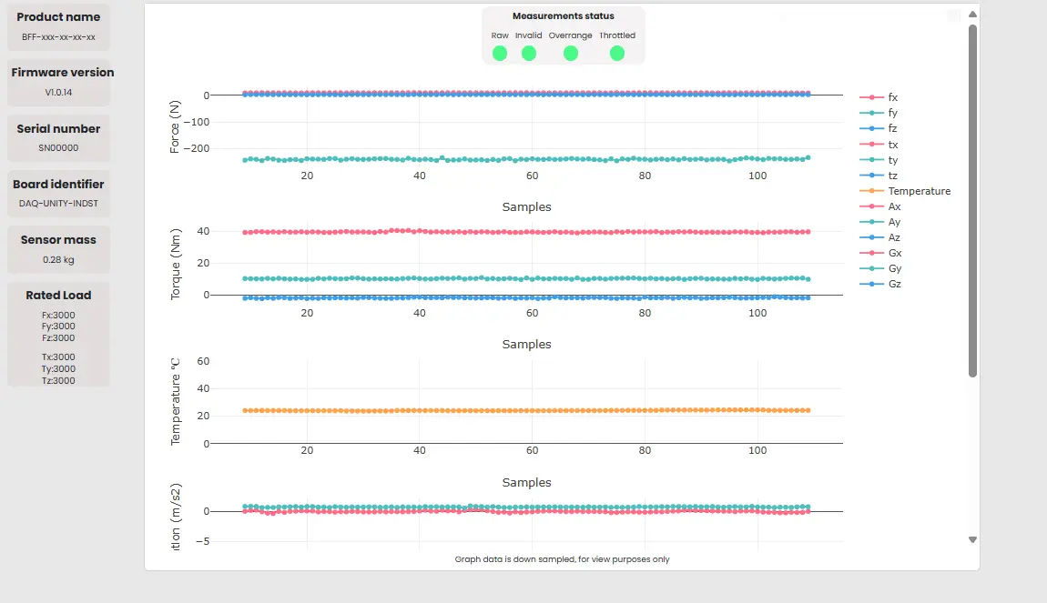
▶ In the pop-up select 460800, and click "Connect". After max 10 seconds, the sensor information on the left side should be populated. Like the Product name, firmware version, etc and the force and Torques are being plotted.
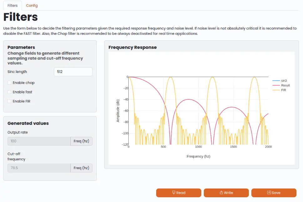
▶ Configure the Sensor's output rate to 100Hz, by clicking the "Configuration" button on the top left. Modify the sinc length to 512 to achieve 100Hz output rate. Double check the Output Rate on the card below together with the Cut-off frequency
▶ To update the configuration of the sensor click the button "Write" and then the "Save" button to save this configuration on the sensor's memory.
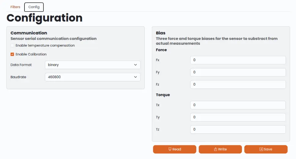
▶ Configure the Sensor's Baudrate, by clicking the "Config" tab on the top. Select the 460800 Baudrate and click the button "Write" and then the "Save" button
Reducing the Baudrate of the sensor will limit (throttle) the output data rate of the sensor.
To evaluate that the new baudrate is sufficient switch to the "Live" View and make sure the "Throttled" Indicator is green.
▶ For the Baudrate changes to apply the sensor has to be restarted, by power cycling it. The new baudrate should be used to connect to the Config Tool
▶ The driver is configuring the sensor on startup, using a configuration file. Fill in in the configuration file below the "Sinc length" that was selected before (512), the Baudrate selected before (460800) and the serial port of the USB-to-Serial Adapter (/dev/ttyUSB* for linux or COM* for Windows)
▶ Download and Install the prebuilt driver using the following command in command line with python and pip installed
pip install bota-driver
▶ Follow the instruction of the python examples to get measurements, there are available for Windows, Linux and Linux ARM architectures.