
Step 1
Unboxing
▶ Make sure all of the parts included in your order has been included in your delivery and there are no signs of damage.
▶ Identify the product Generation. Check on the sensor body for the product name. It starts with "BFT-" for example "BFT-ROKS-ECAT-M8". Make sure your product is part of the list below.
Generation | Product Name |
Gen 0, | BFT-ROKS-ECAT-M8 BFT-ROKA-ECAT-M8 BFT-MEDS-ECAT-M8 BFT-MEDA-ECAT-M8 BFT-DENS-ECAT-M8 BFT-SENS-ECAT-M8 BFT-MENS-ECAT-M8 BFT-LAXS-ECAT-M8 BFT-MEGS-ECAT-M8 BFT-MIPS-ECAT-CG Any product name in the form of BFT-___-ECAT-__ |
▶ Select from the options below the one that best matches your kit.
Step 2
Electrical
Integration
EtherCAT Sensor with
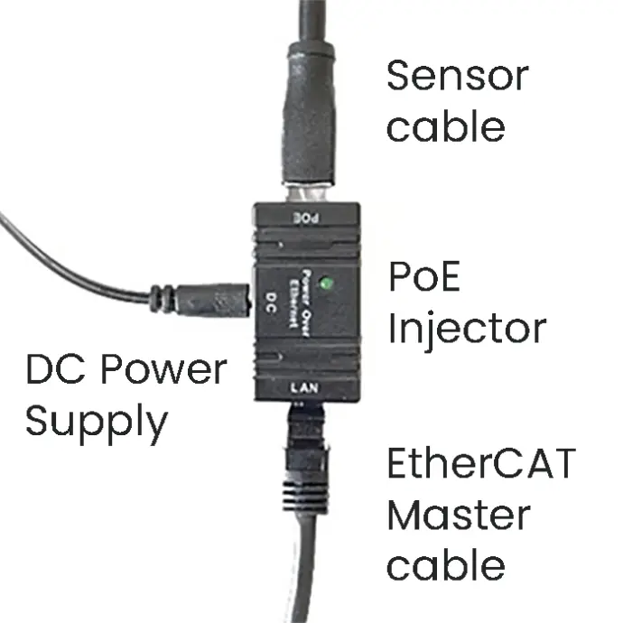
EtherCAT power Injector
▶ Connect the provided cable to the sensor, aligning the key on the cable and sensor connector. Screw the locking nut, till the cable is not moving.
▶ Connect the other end of the sensor cable to the PoE adapter (black box) in the socket labeled "PoE" and connect the provided power supply to the input labeled "DC".
▶ Connect with an Ethernet cable the EtherCAT master device or a computer to the "LAN" labeled connector of the PoE box
▶ Plug the power supply to the wall socket.
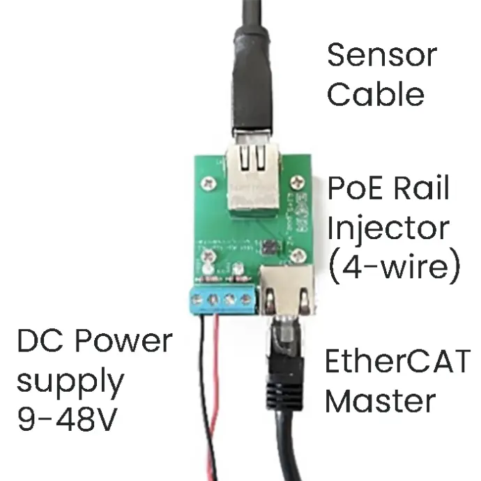
EtherCAT Sensor with
DIN Rail EtherCAT Power Injector
▶ Connect the provided cable to the sensor, aligning the key on the cable and sensor connector. Screw the locking nut, till the cable is not moving.
▶ Connect the other end of the sensor cable to the PoE adapter in the single socket (see piccture above) and connect power through the screw terminals.
This injector allow the sensor to operate with only 4 wires see in the product documents for details
▶ Connect with an Ethernet cable the EtherCAT master device or a computer to the socket next to the screw terminals
Step 3
Mechanical
Integration
Please comply with the following requirements to ensure your sensor’s measurement quality
▶ Avoid mounting with non-rigid parts like 3D printed adapters.
▶ Clean the mounting surfaces from any dirt and debris.
▶ Do not under- or over-tighten the fasteners (see our user manual)
▶ Fix the sensor cable safe and steady on your system such that it does not apply any force to the sensor.
Step 4
Software
Integration

Bota Systems AG has developed a user-friendly driver to simplify the integration of sensors into your applications. The driver is a plug-and-play software package that makes configuring and reading data from Bota Systems' FT sensors easy and efficient for the most popular platforms, including C++, Python and ROS2. For more information see here.
This guide will integrates the sensor with a Python software, for a closed-loop control application that runs in 1000hz.
▶ With the Sensor connected to a Computer that acts as an EtherCAT master, connect to the sensor.
▶ Consult page 12 of the user manual to define the filter parameter "sinc length" for the required output rate of 1000Hz that is 51
▶ The driver is configuring the sensor on startup, using a configuration file. Fill in in the configuration file below the "Sinc length" that was selected before (51), and the ethernet port used for the EtherCAT master to define which ethernet ports are available in your machine run the following command in linux:
ip link show
▶ Download and Install the prebuilt driver using the following command in command line with python and pip installed
pip install bota-driver
▶ Follow the instruction of the python examples to get measurements, there are available for Windows, Linux and Linux ARM architectures.